 |
| ||
|---|---|---|---|
| |
| ||
 |
|||
|
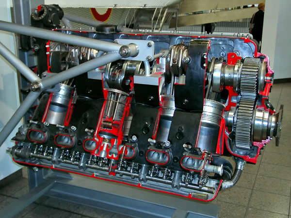
Cutaway view of the Daimler Benz DB 601A. Image from Wikipedia article Daimler-Benz DB 601. | |||
|
The Daimler-Benz DB 600 series, were 12-cylinder, liquid cooled, inverted Vee engines, designed to be right from the very first start. The original engine displacement was 2,069 cu in (33.9L) and utilized direct fuel-injection.
German industry was the leader in direct fuel-injection1 and this gave the Messerschmitt Bf 109 a major advantage over the Supermarine Spitfire. When pulling negative Gs, direct fuel-injection provided a positive fuel feed to keep DB-600 engines running, while carbureted Rolls-Royce Merlin engines would cut-out performing this type of maneuver. Fuel-injection allowed many a Bf 109 pilot to escape a Spitfire on his tail and return to fight another day. The engine had three main features: | |||
| • | It used dry cylinder liners. | • | It had roller bearing connector rods. | • | It had a unique system of attaching the cylinders to the crankcase. |
|
It was used in several aircraft such as the Heinkel 111 and Messerschmitt Bf 110, but its classic use was the Messerschmitt Bf 109. The Bf 109E-5 used the DB 601A, The Bf 109E-6 used the 1,200 hp DB 601N and the Bf 109F used the DB 601E.2
The DB 603's weight of 2,002 lbs. (910 kg) restricted its use primarily to larger aircraft such as the Me 410, the D0 271M bomber, the He 219 night fighter and the experimental D0 335 push-pull twin. |
 |
||
|---|---|---|
|
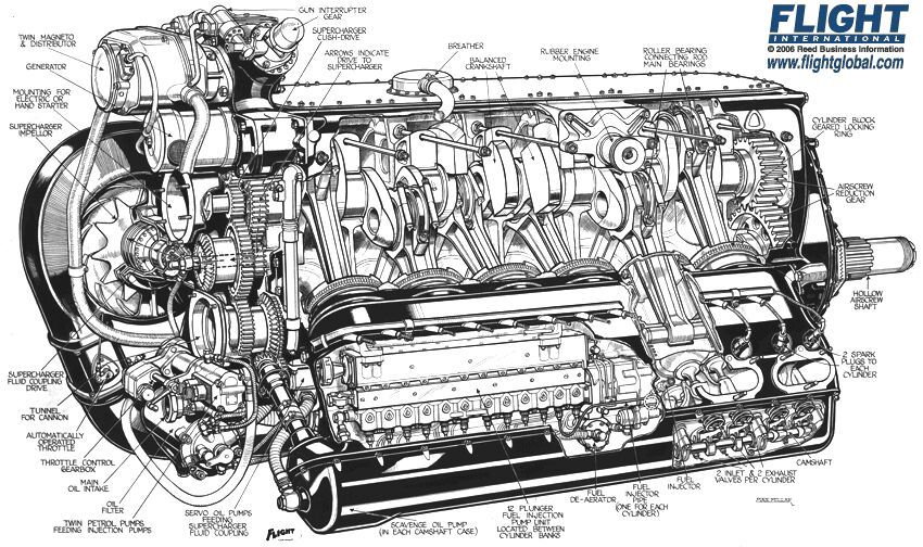
Sectional view of the Daimler Benz DB 601N. |
||
|
The DB 605 was a development of the DB 601 and was very similar in basic construction to that power unit. It was enlarged to 2,179 cu. in. (35.7 L) and the main improvements allowed an increase in the maximum permissible rpm.
Altered valve timing increased the inlet period and improved cylinder scavenging to give greater volumetric efficiency at higher rpm. A completely redesigned cylinder block obtained the maximum possible bore with existing cylinder centers. The new design also repositioned the spark plugs and the crankshaft big-end bearings were also modified.
The DB 606 was two DB 601 engines that were joined, and inclined so that the inner banks were almost vertical, which drove a single shaft. It was a 24-cylinder, liquid-cooled inline engine, of double inverted V or W configuration. The engine was supercharged, with direct fuel injection and geared 0.413 to 1. It was extraordinarily fire prone due to excessive oil and fuel leaks, and its experimental use in the He 177 Greif (Griffin) was one of the Luwaffe's worst fiascos. Heinkel himself attributed the trouble as to the placement of the oil lines being too close to the exhaust system.3 The DB 610 was similar to the DB 606, but was a combination of two DB 605s used on the He 177. It comprised of two inverted vee-12 liquid-cooled engines geared to one propeller. With the introduction of the DB 610 came several improvements, eliminating engine fires, but other minor problems remained, involving the transfer gearbox. |
||
 |
||
|
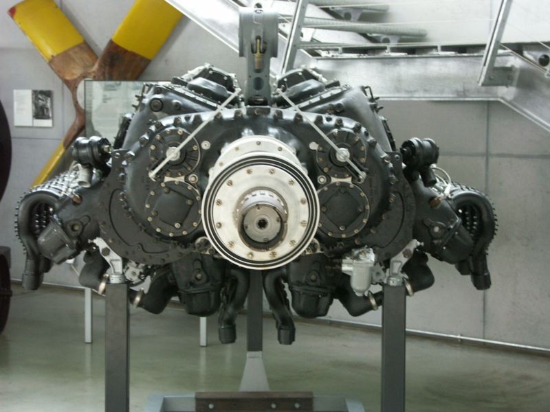
Daimler Benz DB 610. Image from Wikipedia article Daimler-Benz DB 601. |
||
|
Steel cylinder barrels were screwed and shrunk into cast Silium-Gamma alloy cylinder blocks. These dry liners projected beyond the block, providing attachment by means of threaded rings which pull the liners against the finished face of the crankcase. This feature helped to save weight, by not requiring hold-down studs, and avoided the possibility of distortion. Each cylinder had two inlet and two exhaust valves, which were operated by rocker arms with roller-bearings, from a single camshaft mounted in the cylinder head. Valve seats were Stellite alloy and exhaust valves were sodium filled. The pistons were forged light-alloy with concave heads and each piston had a floating wrist pin. There were three compression rings and two oil-scraper rings, with one below the piston pin. The master connecting rods utilized roller bearings, with three rings of 24 rollers each. The slave rod was keyed to the outside of roller race and had a lead-bronze bearing over the race. The forged steel crankshaft was one piece and rotated on seven plain lead-bronze bearings. Eight balance weights were attached to the crank webs and splined at the forward end to receive a reduction gear pinion. The crankcase was light alloy with webs at the main bearings and mounted on a tubular frame at the rear. Below the crankshaft is the propeller shaft with a tunnel, which allowed for installation of a cannon that fired through the shaft. A centrifugal supercharger was located on the port side and driven by a fluid drive from a right angle shaft coming off the crankshaft. The shaft was driven by bevel gears from the crankshaft. Variations in the impeller speed were made through variable pressure from a two-stage engine driven pump, receiving engine oil off the main oil screen. The first stage delivers oil directly to the coupling and the second stage delivery is passed in varying proportions between crankcase and a coupling piston valve, controlled by metering valve, controlled by the inlet pressure. The second stage cuts in at approximately 5,000 feet, and full boost pressure occurs at approximately 11,500 ft. A butterfly throttle valve regulates the supercharger delivery, and a second throttle valve, operated by the pilot, controls the engine manifold pressure. The first throttle is controlled by pressure between two throttles. Increased boost for take-off is controlled by a geared mechanism. The fuel/air mixture is delivered by the supercharger to a large diameter looped manifold. Lubrication is a dry-sump type with gear type oil pumps. Oil is sprayed directly on the reduction gears. The main oil pressure line feeds the crankshaft bearings and secondary oil lines feed the supercharger oil pump. Oil scavenging pumps are located at rear end of the camshafts. Propeller reduction gears are single spur type and there were provisions for a controllable-pitch full-feathering propeller. A centrifugal fluid pump circulated equal parts of water and ethylene-glycol for engine cooling. |
||
| Specifications: | |||||
|---|---|---|---|---|---|
| Daimler-Benz DB 600 Series | Model: | DB 600 | DB 601 | DB 603 | DB 605 | DB 610 |
| Cylinders: | 12 | 12 | 12 | 12 | 24 |
| Configuration: | Inverted V, Liquid cooled | Inverted V, Liquid cooled | Inverted V, Liquid cooled | Inverted V, Liquid cooled | Inverted W, Liquid cooled |
| Horsepower: | 1,000 hp (745 kW) |
1,360 hp (1,014 kW) |
2,830 hp (2,110 kW) |
1,475 hp (1,099 kW) |
2,450 hp (1,826 kW) |
| RPM: | 2,400 | 2,600 | 2,830 | 2,800 | 2,800 |
| Bore and Stroke: | 5.9 in. (150 mm) x 6.3 in. (160 mm) |
5.9 in. (150 mm) x 6.3 in. (160 mm) |
6.4 in. (162 mm) x 7.1 in. (180 mm) |
6.1 in. (154 mm) x 6.3 in. (160 mm) |
6.1 in. (154 mm) x 6.3 in. (160 mm) |
| Displacement: | 2,069 in.3 (33.9 liters) |
2,069 in.3 (33.9 liters) |
2,715 in.3 (44.5 liters) |
2,179 in.3 (35.7 liters) |
5,438 in.3 (71.4 liters) |
| Weight: | 1,510 lbs. (686 kg) |
1,540 lbs. (700 kg) |
2,002 lbs. (910 kg) |
1,663 lbs. (756 kg) |
3,476 lbs. (1,580 kg) |
| Endnotes |
|---|
|
1. Martin C. Windrow. Aircraft in Profile, Volume 2, The Junkers Ju 888. Garden City, NY: Doubleday and Company Inc., 1965. 4. 2. Martin C. Windrow. Aircraft in Profile, The Messerschmitt Bf 109E. Surrey, England; Profile Publications Ltd., 1965. 8. 3. Herschel Smith. The History of Aircraft Piston Engines. Manhattan, Kansas; Sunflower University Press, 1986. 86. 4. Glenn D. Angle, ed. Aerosphere 1943. New York: Aerosphere Inc. 1944. B-93. |
© Larry Dwyer The Aviation History Online Museum.
All rights reserved.
Created November 5, 1998. Updated June 22, 2014.