|
 |
||||||
|---|---|---|---|---|---|---|---|
| Airships of 1927 |
 |
 |
 |
 |
 |
||
 |
 |
 |
 |
 |
|||
 |
||
|
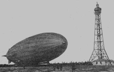
Advantages of Rigid Type Airships--Airship Frame Construction--Large Airships Projected--Army Non-rigid Dirigibles--Requirements of Airships for Civilian Flying. Advantages of Rigid Type Airship. Before describing typical lighter- than-air craft or airships that have received actual commercial as well as military usage, it may be well to briefly review some of the advantages of the rigid type, which is the one that lends itself most easily to large structures and which is also the safest of the three types we have previously reviewed in Chapter II which is devoted to a consideration of the elementary principles underlying airship construction and application. Rigid airships have made longer single flights than other types and have flown more hours and miles without refueling than any other form. The rigid airship is said to be the fastest large vehicle of transportation that engineering ability of man has yet evolved. The Navy Airship Los Angeles, shown near the mooring mast at Lakehurst, N. J. to which it may be anchored is depicted at Fig. 315. A design of the new 6,500,000 cubic foot capacity ship recently authorized by Congress is shown at Fig. 316 flying over a battleship at an elevation of about 1,500 feet. The rigid airship, owing to its large size and light weight can carry more load than any other type of aircraft. It is independent of topography as oceans and continents are but areas to fly over. Land vehicles must stop when they reach water, water transport must stop when the ship is docked.
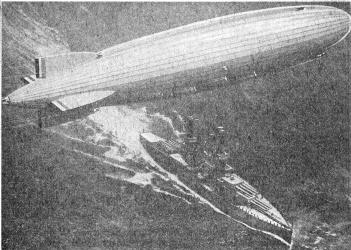 Fig. 316. New Airship that will have over three times the gas capacity of the Los Angeles, as it will Look Flying over Battleship New Hampshire. Airship Frame Construction. The rigid airship, because of its bulkhead system, in which the lifting gas is carried in 16 to 20 cells, has a much greater safety factor than the types in which the gas is carried in only one or two containers. In event of damage to one or two cells, the ship can continue its journey and repairs can be made to a leaky gas cell while in flight.
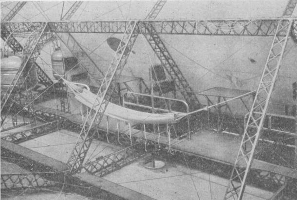 Fig. 317.--Crew's Quarters on Bodensee, a German Zeppelin. Note Construction of Duralumin Girders Built Up of Numerous Small Pieces. The rigid ship has a complete metal framework. Girders extend from nose to tail, or in nautical parlance, from stem to stern. Ring girders set at intervals brace the longitudinals and are themselves internally reinforced by cross girders and tension wire bracing. The entire framework is enclosed by a network of wiring and the whole is streamlined or faired to minimize air resistance with a fabric covering.
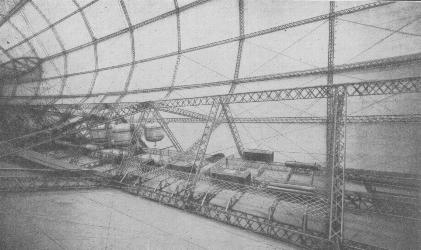 Fig. 318.--View of the Interior of the Zeppelin Rigid Airship, the Bodensee, Showing how Ring Frames and Longitudinal Girders Form Light Framework of Hull. The view of the crew's quarters on the Bodensee, a German air liner at Fig. 317, shows the triangular keel member with the cat-walk by which the crew can travel from one end of the ship to the other and gain access to the different gas bags. The character of the longitudinal duralumin girders and the way they are braced by the ring girders is clearly shown at Fig. 318. This depicts that portion of the hull where one set of fuel tanks are located. The view at Fig. 319 shows the interior with the deflated gas cells hanging from the top-most longitudinal ready for inflation.
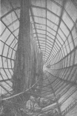 Fig. 319.--Interior View of the Framework of the Zeppelin "Bodensee" Showing Deflated Gas Bags of Gold Beater's Skin Hanging from the Top of the Structure. The outer skin is in place and the large size and extreme lightness of the structure is clearly shown. The passenger cabin of the Deutschland, another rigid dirigible of the Zeppelin series is shown at Fig. 320. Wicker chairs are used because of their light weight and the interior structure of the cabin can be determined by study of the illustration.
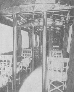 Fig. 320.--Interior View of the Passenger Cabin of the Deutschland Showing Comfortable but Light Wicker Arm Chairs and Large Windows for observation Purposes.
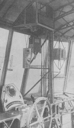 Fig. 321.--Part of the Control Car of the "L 59" Showing Wheel for Elevator Control and Instruments for Altitude Indication for Guidance of Helmsman. A Similar Installation on the other Side of Cabin Controls Vertical Rudder and Horizontal Movements. The control of a Zeppelin type airship is not as simple as that of an airplane and no one man is at the controls. Special controls are provided for the elevators and still another set for the vertical rudders. The elevator control of the L59 with the instruments for altitude navigation is shown at Fig. 321. Control is by a large wheel similar to the steering wheel of a ship. Directional control is by a similar wheel at another part of the control car.
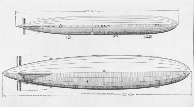 Fig. 322--Drawings Comparing the Size of the U. S. Navy Shenandoah or ZR1 with a Proposed Military Airship Having More than Three Times its Cubical Contents. Large Airship Projected. The largest of the United States Navy airships, the Shenandoah was 600 feet long with a capacity of 2,115,000 cubic feet. The projected airship designed by the engineers of the Goodyear- Zeppelin Company, while it has over three times the capacity of the Shenandoah will be only 100 feet longer and will be of such size that it may be housed in the Lakehurst hangar. The illustration at Fig. 322 shows how the new ships authorized by congress will compare with the Shenandoah. The control car will be built into the hull and streamlined. Engines of 4,800 horsepower, giving a speed of 90 miles per hour with fuel for from 5,000 to 8,000 miles will drive the ship. The air screws will be fitted in tilting mountings, which will turn in a 90 degree arc to help force the ship upward or downward as desired and greatly aid in controlling the huge vessel. It will embody the proved structural advantages of some 135 ships built in the past. (a) Multiple gas cells which function like bulk-heading on a steamship, so that if one or more cells fail the ship will still remain aloft: (b) The triple cover system, one cover to hold the lifting gas, one consisting of the shape-forming duralumin frame-work, and an outer cover to shed rain and snow, to reflect rather than to absorb heat, and to present a fair surface; (c) invulnerability against lightning; (d) accessibility to inspection and repair.
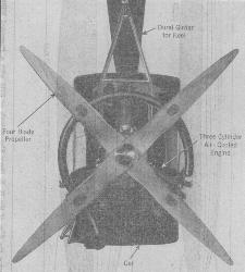 Fig. 323.--Rear View of Power Car of Small Non-Rigid Type Dirigible Showing Installation of Wright "Gale" Engine and Four Blade Metal Propeller. It will however present certain new features as well of far reaching importance: (a) A double or triple keel giving added longitudinal strength comparable to the breaking strength of one length of metal, as against two or three bolted together; (b) a new type of ring girder each internally braced and structurally self sufficient, which (c) will permit the control car and even the power cars to be built within the hull; (d) even fuller accessibility to continuous inspection and permitting repairs to be made even in flight; (e) the use of new fuels to conserve helium and reduce weight.
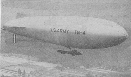 Fig. 324.--View of U. S. Army TC-4 Non-Rigid Type in Flight Taken from official Photograph of U. S. Army Air Corps. Army Non-Rigid Dirigibles. The non-rigid dirigible is the smallest of the three types as the largest now being built in the United States for the Army and Navy service have a gas capacity of about one-tenth that of the Los Angeles. Under ordinary conditions a 230,000 cubic foot non-rigid has a cruising radius of from 500 to 1,000 miles and an air endurance of from 18 to 24 hours. Such airships are essentially motorized free balloons and the engines are carried in a car attached to the lower side or bottom of the bag. The Pilgrim, a small non-rigid previously described with a gas capacity of 50,000 cubic feet has a speed of 50 miles per hour and is propelled by a Wright "Gale" three-cylinder engine as shown at Fig. 323. This small ship was built to carry four passengers. The gas in non-rigid ships, as in the army TC types, as shown at Fig. 324 is contained in a single bag, but an inner two compartment bag, called the ballonet, is filled with air to keep the main container properly distended because the air pressure can be made to compensate for variations in gas pressure in the bag. These ships have a capacity of about 200,000 cubic feet, are 196 feet long overall and 47 feet in extreme height. The hull diameter is 33.5 feet. The fineness ratio is 4.4 to 1. The total lift is 11,584 pounds of which the useful lift is about 4,000 pounds. The gross weight per horsepower is 38.6 pounds. Two Wright Type I water-cooled engines of 150 horsepower each were provided on the first ships of this series but these have been replaced on later types with two Wright J1 engines, which are nine-cylinder radial air-cooled types driving tractor propellers 9 feet 10 inches in diameter. It is claimed that the saving of 400 pounds over the water-cooled installation permits an increase of speed from 54 to 60 miles per hour; with an increase in range of 10 per cent.
|
Return to Aircraft Theory Index
© The Aviation History Online Museum. All rights reserved.
Created June 3, 2002. Updated June 7, 2015.